Notice:
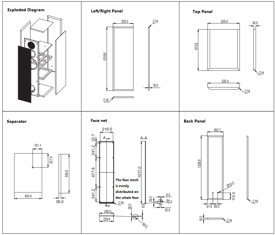
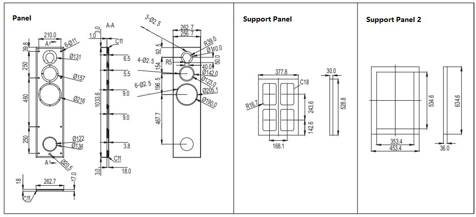
If the drawings given in the kit are different from those published in the advertisement, please refer to the drawings in the kit;
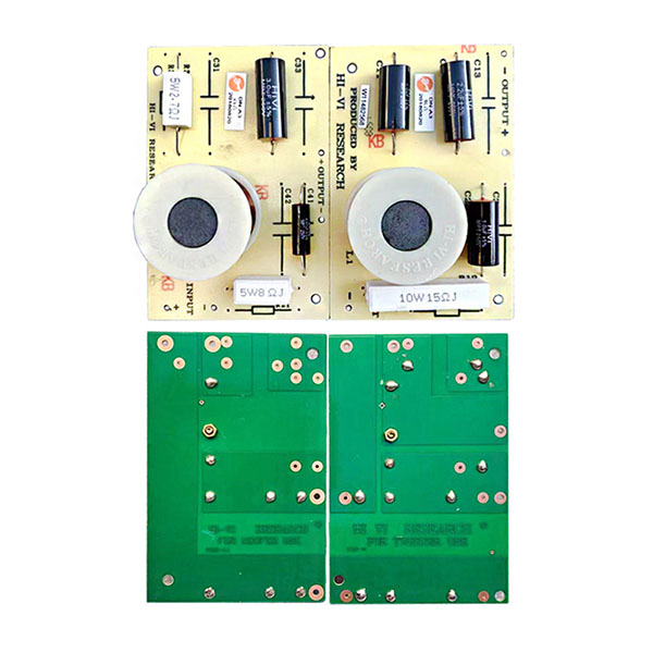
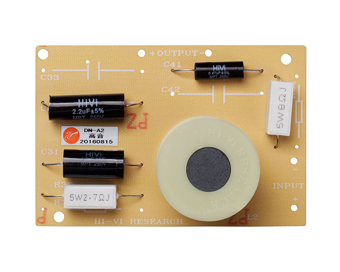
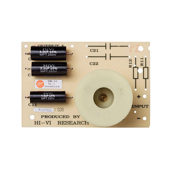
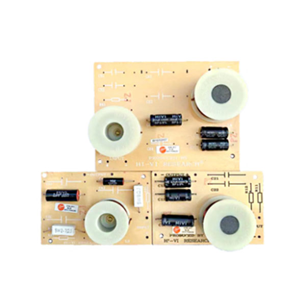
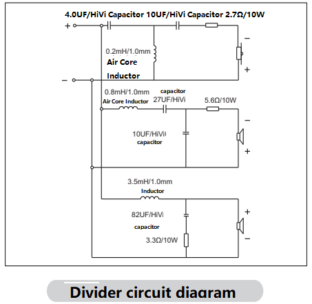
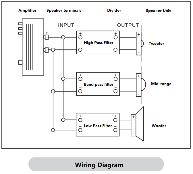
Step 2: Install the Crossover
Notice:
1. Compare the corresponding length to intercept the fever wire and the welding divider connection in the box;
2. The welding polarity must be correct; (The red line of the general fever line or the word is the positive pole, and the silver-white line or no word is the negative pole.)
3. Install the frequency divider on the rear box panel (or side panel) opposite the opening of the corresponding unit, and pay attention to adding a square buffer.
Step 3: Install the Junction Box
a. Take out the junction box, turn it over to the back of the junction box, and you can see that there are four soldering lugs, marked with "+, -", divided into upper and lower groups.
b. Pass the "positive" and "negative" pole fever wires of the input end of the tweeter through the box board from the opening of the box junction box, and weld them to the "+, -" solder lugs of one group of the junction box respectively.
c. Pass the "positive" and "negative" pole fever wires of the input end of the bass crossover through the box board through the opening of the box junction box, and weld them to the "+, -" solder lugs of the other group of the junction box respectively.
d. Confirm that there is no short circuit or virtual welding between the wire ends and the solder tabs, and then fasten the junction box (gasket) to the box with screws. (Note that the terminal is upward, that is, "left negative, right positive".) Note: The high and low frequencies are designed as a group of inputs, and the upper and lower terminals of the junction box are connected by connecting pieces, so the input wire can be soldered on one of the upper and lower sets of solder pieces. .
Step 4: Fill with sound-absorbing cotton. The filling ratio is: 30%.
Step 5: Solder the internal wiring and install the speaker.
Notice:
a. The welding polarity must be correct. Generally speaking, the wiring terminals of the speaker unit have positive (+), negative (-) marks or different thicknesses. (The thick end with red is the positive electrode, and the thin end is colorless for the negative electrode.)
b. Buffer pads must be added to install the speakers and they must be leveled and pressed to prevent air leakage.
c. During installation, the mid-high frequency panel should be at the same level as the outer surface of the speaker, so that a flat mid-high frequency sound pressure curve can be obtained.